Massive MIMO (mMIMO) and beamforming are buzzwords widely used in the telecom industry when referring to 5G and latest advancements of LTE. The challenge is that MIMO comes in many different variants, some of them having been in use already for years in legacy LTE networks.
SU-MIMO vs. MU-MIMO
In legacy LTE, the term MIMO usually refers to Single User MIMO (SU-MIMO). In Single User MIMO, both the base station and UE have multiple antenna ports and antennas, and multiple data streams are transmitted simultaneously to the UE using same time/frequency resources, doubling (2×2 MIMO), or quadrupling (4×4 MIMO) the peak throughput of a single user.
In MU-MIMO, base station sends multiple data streams, one per UE, using the same time-frequency resources. Hence, MU-MIMO increases the total cell throughput, i.e. cell capacity. The base station has multiple antenna ports, as many as there are UEs receiving data simultaneously, and one antenna port is needed in each UE.
Beamforming – principle of operation
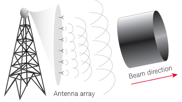
Terms beamforming and mMIMO are sometimes used interchangeably. One way to put it is that beamforming is used in mMIMO, or beamforming is a subset of mMIMO. In general, beamforming uses multiple antennas to control the direction of a wave-front by appropriately weighting the magnitude and phase of individual antenna signals in an array of multiple antennas. That is, the same signal is sent from multiple antennas that have sufficient space between them (at least ½ wavelength). In any given location, the receiver will thus receive multiple copies of the same signal. Depending on the location of the receiver, the signals may be in opposite phases, destructively averaging each other out, or constructively sum up if the different copies are in the same phase, or anything in between. Beamforming is further divided to subcategories as explained in the following chapters.

Digital beamforming (aka. Baseband beamforming, aka precoding)
The signal is pre-coded (amplitude and phase modifications) in baseband processing before RF transmission. Multiple beams (one per each user) can be formed simultaneously from the same set of antenna elements. In the context of LTE/5G, MU-MIMO equals to digital beamforming. Multiple TRX chains, one per each simultaneous MU-MIMO user, are needed in the base station. Digital beamforming (MU-MIMO) is used in LTE Advanced Pro (transmission modes 7,8, and 9) and in 5G NR. Digital beamforming improves the cell capacity as the same PRBs (frequency/time resources) can be used to transmit data simultaneously for multiple users.
Analog beamforming
The signal phases of individual antenna signals are adjusted in RF domain. Analog beamforming impacts the radiation pattern and gain of the antenna array, thus improves coverage. Unlike in digital beamforming, only one beam per set of antenna elements can be formed. The antenna gain boost provided by the analog beamforming overcomes partly the impact of high pathloss in mmWave. Therefore analog beamforming is considered mandatory for the mmWave frequency range 5G NR.
Hybrid beamforming
Hybrid beamforming combines the analog beamforming and digital beamforming. It is expected that mm-wave gNB (5G base station) implementations will use some form of hybrid beamforming. One approach is to use analog beamforming for coarse beamforming, and inside the analog beam use a digital beamforming scheme as appropriate, either MU-MIMO or SU-MIMO.
Massive MIMO
The most commonly seen definition is that mMIMO is a system where the number of antennas exceeds the number of users. In practice, massive means there are 32 or more logical antenna ports in the base station It is expected that NEMs will start with a maximum of 64 logical antenna ports in 5G.
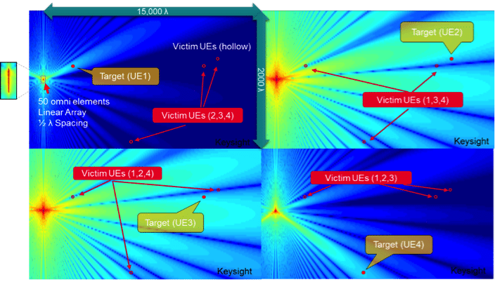
Figure 2 illustrates how mMIMO works in practice. An antenna array of 50 omni elements, with ½ wavelength spacing in between the antenna elements is used. The 50 elements transmit 4 distinct streams of data via 4 logical antenna ports, one stream for each UE. All four streams are transmitted using the same physical resource blocks, i.e. the same time/frequency resources. The data streams do not interfere between each other because each of them has a distinct radiation pattern, where the signal strength in the direction of the target UE is optimized, and in the directions of the other UEs (victim UEs) the signal strength is minimized.

In MU-MIMO/mMIMO, the base station applies distinct precoding for the data stream of each UE where the location of the UE, as well as the location of all the other UEs, are taken into account to optimize the signal for target UE and at the same time minimize interference to the other UEs. To do this, the base station needs to know how the downlink radio channel looks like for each of the UEs.
Beam-based coverage measurements in 5G
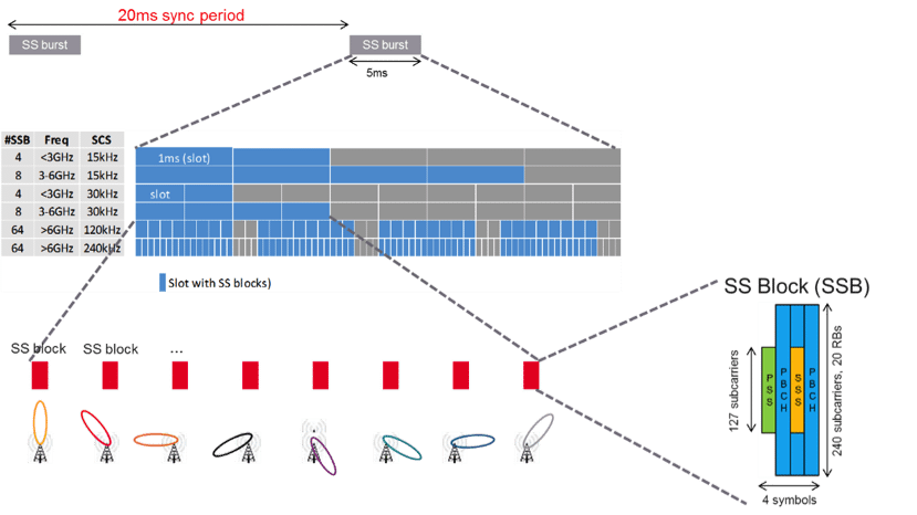
The coverage is beam-based in 5G, not cell based. There is no cell-level reference channel from where the coverage of the cell could be measured. Instead, each cell has one or multiple Synchronization Signal Block Beam (SSB) beams, see Figure 3. SSB beams are static, or semi-static, always pointing to the same direction. They form a grid of beams covering the whole cell area. The UE searches for and measure the beams, maintaining a set of candidate beams. The candidate set of beams may contain beams from multiple cells. The metrics measured are SS-RSRP, SS-RSRQ, and SS-SINR for each beam. Physical Cell ID (PCI) and beam ID are the identifications separating beams from each other. In field measurements, these metrics can be collected both with scanning receivers and test UEs. Hence, SSB beams show up as kind of new layer of mini-cells inside each cell in the field measurements.
As can be seen from Figure 3, the different SSBs (beams) of a cell are transmitted at different times. Therefore, there is no intra-cell interference among the SSB beams, and at least the scanning receivers should be able to detect also extremely weak SSB beams, even in presence of a dominant, strong beam from the same cell. As an example, let’s imagine a place of poor dominance in an LTE network, where a scanner or a test UE detects reference signals from 6 different cells. If it were a 5G network, the device could see, for example, six beams of each sox cells, in total 36 reference signals. Provided of course that the scanner or test UE is fast enough to catch all these signals. The performance of the UEs as well as scanners is yet to be seen both in the spec sheets and in practice.

Of course, it must be kept in mind that 5G can operate without beamforming, in which case there would be one SSB beam covering the whole cell area, and all the coverage testing methodology would default back to same as in LTE as SSB beam equals to cell in that case.
How to test capacity gain of Massive MIMO
Capacity gain is achieved only when multiple UEs are generating downlink traffic simultaneously. There are many variables impacting the real-life gain provided by the mMIMO.
The spatial distribution of cell users has a big impact. Ideally, the UEs should be scattered across the cell area. If all users are packed in the same location, for example around the same table in a cafeteria, it becomes impossible to isolate the users to different beams that do not overlap. The minimum horizontal and vertical spatial separation between UEs may differ depending on the number of physical antenna elements in the gNB antenna panel in the horizontal and vertical dimensions..
The signa- to-noise-ratio of each user, as well as the multipath propagation profile impact the achievable performance. The scheduling decisions, as well as whether MU-MIMO is to be used or not, are done by every 1ms slot by the gNB. The gNB scheduling and link adaptation algorithms are proprietary, not defined in 3GPP. Hence it is an area where the network equipment manufacturers can differentiate from each other. The performance of the mMIMO has a major impact in the system capacity of the 5G network. Hence, it is in the best interest of the operators to verify the field performance of massive MIMO implementations as part of the vendor selection and network acceptance processes.
Summary
When testing the capacity gain of mMIMO, there needs to be multiple test UEs distributed in the cell area, each performing active bulk data transfer testing against a test server simultaneously. As part of the test setup, it is important to ensure that the core network and backend server have sufficient bandwidth, so that the radio interface is the only bandwidth bottleneck during the test. Multi-threaded data download can be used in the tests to remove sub-optimal impacts of TCP flow control. The different scenarios to be tested may include UEs close to each other to test the threshold spatial separation where mMIMO can still provide gain, vertical distribution of UEs (one in each floor of a high-rise building), horizontal distribution of UEs, line of sight UEs vs non-line of sight UEs with rich multipath propagation environment, cell edge vs. cell center, moving UEs, or any combination of the above.
At Keysight Nemo Wireless Solutions we have hands-on experience on the LTE massive MIMO field verification. The principles of mMIMO operation are the same in LTE and 5G. Therefore, the test system and methodology developed and tested for LTE mMIMO verification can be reused for 5G. Keysight’s Nemo measurement solutions consist of field test units with form factors ranging from single smartphone with special test FW/SW to PC-controlled chassis housing multiple test UEs, and Nemo Cloud, the central cloud-based control SW for the field units.

About the author. Matti Passoja, Director, Solution marketing at Keysight Wireless Network Solutions. Matti is responsible for solution marketing of 5G and IoT at Keysight Wireless Network Solutions. This includes sales/channel enablement, outbound marketing, Go To Market planning. Further Matti has 10+ year experience in D and product management of RAN data collection and analytics solutions.

